Bare metal code on the Raspberry Pi

I’ve had my Raspberry Pi for a while now, and it makes a great little Linux system.  I’ve even been exercising the graphics capabilities with our game Iridium Rising

But one thing I’ve been meaning to do is go straight to the bare metal – just run some code on the CPU with no OS to get in the way.  Luckily I’m not alone and there’s a decent forum thread on how to get started.

There was still a bit of work to pull everything together – so I’ve whacked up a git repo with a readme on how to get everything set up.

The end result is the OK light on your Pi blink, but everything is set up ready to do something a bit more interesting.

Pi and Arduino

You’ve probably seen Dr. Monk’s blog on using Pi and Arduino, but what if you don’t have the Arduino software installed on a nearby computer?  (Or, like me, you are just perverse and want to make something work only using the RasPi.)

I had a quick look at getting the Arduino IDE running on the Pi, but that’s likely to be effort because the Arduino page specifically states you must use Sun’s version of Java or it won’t compile.  That’s an issue because Sun (now Oracle) haven’t made a version of Java for the Pi (so far).

So, time to learn how to program an Arduino without using the IDE.  These instructions basically worked first time for me, except I had an issue with actually programming the Arduino which turned out to be because the USB hub I was using to provide power was only giving around 4.5v to the Pi – which is out of spec.  (Aside: That may well be what caused the problem with the Sandisk Cruzer USB flash drive – I can’t tell if it works now because the drive has gone permanently write protected, which is a bit annoying)

Note these instructions are for the Arduino Uno.

In summary you need to install the AVR toolchain:

sudo apt-get install gcc-avr avr-libc avrdude

Create your program for the Arduino, say as blink.c (source heavily based on the above link):

#include <avr/io.h>
#include <util/delay.h>
#define BLINK_DELAY_MS 500
int main (void)
{
  /* set pin 5 of PORTB for output*/
  DDRB |= _BV(DDB5);
  while(1) {
    /* set pin 5 high to turn led on */
    PORTB |= _BV(PORTB5);
    _delay_ms(BLINK_DELAY_MS);
    /* set pin 5 low to turn led off */
    PORTB &= ~_BV(PORTB5);
    _delay_ms(BLINK_DELAY_MS);
  }
  return 0;
}

Now I created a short shell script “program.sh” to compile and program the board, it takes the C file to compile as an argument, e.g. ./program.sh blink.c

#!/bin/bash
if [ -z $1 ]; then
 echo "Usage $0 <source.c>"
 exit
fi
FILE=$(echo $1 | sed 's/\..*//')
rm $FILE.o $FILE.elf $FILE.hex
avr-gcc -Os -DF_CPU=16000000UL -mmcu=atmega328p -c -o $FILE.o $1
avr-gcc -mmcu=atmega328p $FILE.o -o $FILE.elf
avr-objcopy -O ihex -R .eeprom $FILE.elf $FILE.hex
avrdude -c arduino -p ATMEGA328P -P /dev/ttyACM0 -b 115200 -U flash:w:$FILE.hex

Run that over your C file and you should see output as your Arduino is programmed, and then the LED on the Arduino starts to flash.

Source in easy to pull form is over on github.
First slice of Raspberry Pi

My RaspberryPi arrived yesterday! I’ve been anticipating it for so long I almost wasn’t expecting it, despite the dispatch note from Farnell on Friday.

I spent a while yesterday struggling to get it booting, due to an SD card it didn’t like. This is apparently a firmware issue the Raspberry Pi foundation are aware of and are hoping to resolve, but at the moment, especially as there are so few Pis around, it’s a bit of a lottery whether you have a good card or not. The particular Class 4 SDHC SanDisk card I had was no good, but an older 8 GB SanDisk card from my camera worked fine.

Once it came to life the HDMI output to my TV worked straight away.  I haven’t tried it with my LCD display yet.  I had a quick play in X – Midori wouldn’t run enough of the main twitter site, but was good enough to tweet from the mobile version.  I then enabled sshd and so it can run headless, this was simply a case of renaming a boot.rc file in /boot, can’t give the exact command because I don’t remember the original file name, but it was obvious.

I was a bit disappointed that my 16GB Sandisk Cruzer Blade USB stick didn’t work – dmesg showed various kernel errors when I first plugged it in.  Second time (in the other USB port, though don’t know if that really made the difference) it came up and I could mount it, but when I tried writing to it I got some DMA errors from the kernel and it went read-only.  I haven’t done any Linux kernel debugging before, but I suspect here might be where I start!

Today, I thought I’d give the GPIO a quick test – after all, that was one of the things that got me most excited about the Pi in the first place.

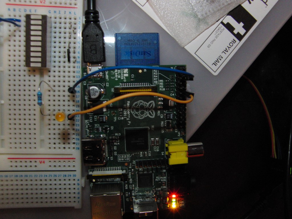
Note, there is no protection on the GPIO so you should proceed with caution.  I set up a simple LED with an over the top 510 ohm resistor to ensure I wasn’t going to draw too much current from the GPIO:

I’m using GPIO 18, which is 6 from the top on the right hand row, and its connected to ground (3rd from the top on the same row) via a yellow LED and the aforementioned resistor.

You can make it blink straight from the shell:

pi@raspberrypi:/dev$ sudo bash
root@raspberrypi:/dev# echo "18" > /sys/class/gpio/export
root@raspberrypi:/dev# echo "out" > /sys/class/gpio/gpio18/direction
root@raspberrypi:/dev# echo "1" > /sys/class/gpio/gpio18/value
root@raspberrypi:/dev# echo "0" > /sys/class/gpio/gpio18/value
root@raspberrypi:/dev# while ((1)); do echo "1"; sleep 0.2; echo "0"; sleep 0.2; done > /sys/class/gpio/gpio18/value
^C
root@raspberrypi:/dev# echo "0" > /sys/class/gpio/gpio18/value
root@raspberrypi:/dev# echo "18" > /sys/class/gpio/unexport

The video shows it blinking on and off:

Stepper Motor

I bought a little stepper motor and H-bridge.  The plan eventually is to integrate it into a steampunk costume, but today I was just getting it wired up to try it out.

I wired things up according to the 4-wire diagram for a bipolar stepper motor from the excellent instructions here.

Here it is running backward and forward off a 9V battery, with the wax off a bottle of whisky on top!

The code is on github, as ever.

RaspberryPi bits

Along with half the rest of the known universe, I’m eagerly awaiting the release of the RaspberryPi.

The Pi is a fullly fledged computer that costs only $35 (or in future $25 for a model with less memory, no ethernet and just one USB socket).  It has plenty of potential for fun projects – there are some general purpose IO pins, and it should be possible to power it off a battery – or just for replacing my old Linux server with something silent, low power and it is just the size of a credit card!

The first batch is due to finish manufacturing on 20th Feb, so hopefully they will be shipping in early March and I’m hoping to manage to get my hands on one (though there’s going to be stiff competition, as there are only 10,000 boards in the first batch and well over 50,000 people that want one!)

The $35 only buys you the board itself – you need to supply your own power, SD card, keyboard, monitor, cables and everything else.  So I thought it was about time to get stocked up on the required subsidiary hardware.  I’ve ordered a couple of 4GB SD cards and a 16GB USB drive, a 4 port powered USB hub (which I’m hoping will be able to power the Pi – if that doesn’t work out I can use the charger from an HTC Desire as a temporary measure), and an HDMI to DVI cable (the Pi doesn’t have a VGA port).

All in all, I ended up paying more for this than the RaspberryPi itself is going to cost!  This got me thinking – one of the intended purposes of the Pi is for use in schools.  They are likely to have some of this stuff (keyboards and mice, for instance), but a combined power source, USB hub and WiFi/wired internet connection would be a very handy combination.  You could even make it power 2 Pis, with 2 independent hubs, then you could sit it between 2 students who were playing with the Pis.  I should post something on their forum…

Charlieplexing

Someone at work mentioned charlieplexing, which I thought was rather cool.  And potentially useful for debugging things on the ATTiny where you don’t have many pins.

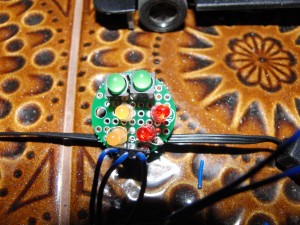
So in a break from playing with the Scalextric bits, I’ve made up a little board with 6 LEDs and a 3 pin header, using a small circular proto board from proto-pic:

And here it is in action:

The code would be very straightforward if I hadn’t overused the ?: operator and bit operations.  Here it is for you to puzzle over:

  for (int j = 0; j < 64; j++)
  {
    for (int k = 0; k < 100; k++)
    {
      for (int i = 0; i < 6; i++)
      {
        if (j & (1 << i))
        {
          pinMode(5, (i < 4) ? OUTPUT : INPUT);
          pinMode(6, ((i < 2) || (i >= 4)) ? OUTPUT : INPUT);
          pinMode(7, (i >= 2) ? OUTPUT : INPUT);
          digitalWrite(5, (i & 1) ? HIGH : LOW);
          digitalWrite(6, (i & 1) ? LOW : HIGH);
          digitalWrite(7, (((i & 4) >> 2) ^ (i & 1)) ? LOW : HIGH);
        }
        else
        {
          pinMode(5, INPUT);
          pinMode(7, INPUT);
          pinMode(6, INPUT);
        }
        delay(1);
      }
    }
  }

The outer loop selects one of the 64 possible combinations of the 6 LEDs.

The inner loop lights or does not light each LED in turn.  Because it cycles through the LEDs fast enough all the lit LEDs appear lit simultaneously.

The middle loop just runs round lighting the same set of LEDs hundred times before moving onto the next set.

Accelerometer display

I thought it was about time I put my display driving code on the FPGA to good use :-)   So I added the X, Y and Z values to the power value already transmitted from the Arduino, and got the display up and working.

A minor annoyance was the Arduino IDE crashed at one point in a way that was completely unkillable (even kill -9), so I had to reboot my Mac.  Also, my Merc seems to be ill so I’ve moved the accelerometer over to the Porsche with the new engine – which seems to be running very smoothly now.

The end result is here:

The dot moves up/down for acceleration/deceleration and side to side as the car goes round corners.  Or it’s meant to – as you can see, it is certainly skipping about, but you need a reasonable amount of imagination to believe it is related in any way to the cars movement…  This could be harder than I first thought!

I think the next step will be to try and improve the data rate from the car – currently I can only hope to get back 10 readings/sec.

As ever, I’ve updated the Arduino and FPGA repos with the latest code.

Feedback from the car

Now I have a reasonable RF link, I’ve been trying to get the car to drive around the track.

I have a slightly odd setup for controlling the power to the track.  Because I made this up before my Arduino arrived, I’ve got a Xilinx FPGA on a Basys-2 board setup to control the track.  This board is quite handy because it has 8 on-off switches and 8 LEDs (and a variety of other things) on it.

Up until now, I’ve controlled the voltage with the switches.  The design loaded on the FPGA is very straightforward, I’ve got an 12-bit counter counting up at the clock frequency (50MHz), and when the top 8 bits are greater than the value set on the switches, power is applied to the track through a Darlington pair of transistors.

I added a simple serial channel from the Arduino to the FPGA so it could set the voltage.  This was a very straightforward design: 2 wires, a clock and a data line both driven from the Arduino.  Data is sent 1 byte at a time, simply by sending 1 pulse on the clock line, and then 1 bit of data each subsequent time the clock rises.  To make this slightly complicated, the Arduino outputs are at 5V, and the FPGA’s maximum allowed rating on an input pin is 4.4V.  So I’ve got a simple voltage divider to get the inputs down to 2.5V.

Initially, this didn’t quite work – it appears that at the 50MHz frequency of the FPGA the signal was bouncing – I fixed that by ignoring changes in the clock line until it was stable for 16 cycles (I suspect less would have worked, but it doesn’t need to be *that* fast).

I have the value sent from the Arduino displayed on the LEDs on the FPGA so I can see what is going on.  The top switch on the FPGA now selects whether the value from the Arduino or the value set on the rest of the switches controls the power to the track.

My first proof of concept was to simply increase power to the track until the accelerometer detected any movement, and back off until the movement went away, then increase again.  This successfully made the motor hum without the car moving (perceptably).

I now have it set up to increase the power while the accelerometer readings are close to their average values, drop the power if they start deviating a bit, and cut the power significantly if they go over a certain value.  This allows the car to go round the track in fits and starts, but without flying off.

Finally, mchr3k has taken my Manchester library changes and is now hosting the definitive version here.  I’m including that as a submodule in my Arduino repo.  I’ve also made a new repo for the FPGA design.

Improved Manchester library

As mentioned previously, I’m now using a Manchester encoding library linked to from mchr3k‘s blog, and originally posted here, to transmit data from the car back to my Arduino Uno.

I took a bunch of changes from mchr3k, including comments and sorting out the code layout and fixing a couple of bugs.  This now gives a very reliable connection between the car and the receiver – I’m seeing errors well below 1%.

I also wanted to be able to transmit a variable number of bytes (the original code always transmitted just one 16-bit integer) and have now got that coded up and working.

The full code with comments is available on github.  See the code for a good description of how it all works – it is now commented fairly well.  I hope that this will be a useful resource for other people trying to use RF modules with the ATTiny.

In the medium term I’m hoping to improve the library further to deal with interference better – right now the code just gives up if a transition occurs at an invalid time.  I hope that if I do that I’ll be able to turn the bit rate up a bit.

It would also be nice to produce an interrupt driven receive side, to allow the receiver to avoid having to sit in the receive loop all the time.  That’s not my priority right now though.

Racing

I never got round to trying out my new motors yesterday, so I thought I’d give that a go this morning.  I replaced the motor in one of our two old Porsches.

Unfortunately I broke the motor mount slightly when getting the old one out – the old plastic couldn’t take the flex (or maybe I’m doing something wrong, I did seem to have to push very hard!)  Still, the motor seems be in held in well enough to run round with no problems.

The tyres on the Porsche are knackered so it slips all over the place, which makes it rather a challenge to drive.  Unlike the Merc, I couldn’t get it to go round just with a steady voltage.  Hooking up the controller, I had a race between the computer driven (i.e. steady voltage) Merc and me driving the Porsche – the computer won, but I think I did reasonably well considering the lack of grip.

If I can fix up the other Merc then we should be able to have a fairer race.  I’ll get you next time, Gadget!