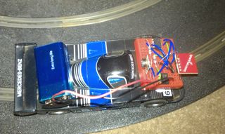
Back from Maplin, I was eager to try out running the accelerometer on the car.
The circuit has now got a little complicated. I was hoping to draw it out but that will take longer than it took to wire up, so you’ll have to do with a description.
I need two voltages – the 9v battery powers the transmitter, and I use a 1k resistor and 3.3v Zener diode to generate 3.3 volts for the accelerometer and ATTiny.
The output from the Tiny now has to be amplified back up to 9v for the transmitter. I had a TS358 Op Amp around that I’m using to achieve that. The positive input to the Op Amp is connected to the output from the Tiny, and the negative input to a voltage divider of two 100k resistors, between 3.3v and ground. The result of that is the negative input is held at around 1.6v, so when the Tiny drives the positive input low, the output goes low, and when the Tiny drives the positive input high (3.3v) the output goes high (9v). The output from that then goes to the transmitter.
The result looks like this:
The problems I have now are that transmitting the readings back takes too long – a corner only lasts a few transmits – and I’m still seeing odd bit errors despite the checksum. I hear that there might be a bug in the Manchester library though, so that could explain that.
Plans going forward (not necessarily in order) are to:
- Speed up the transmission (the library is only writing data at 500bps, I think we can do better than that)
- Look into error correction with a Hamming code
- Transmit only the useful range of the accelerometer output, and only at useful resolution
- Get the readings to my FPGA so I can visualize the G force (I already have that driving a 1024×768 display)
- Think about how I’m actually going to control this in software!
